Configuring Manual Bindings
An address binding is a mapping between the IP address and MAC address
of a client. The IP address of a client can be assigned manually by an
administrator or assigned automatically from a pool by a DHCP server.
Manual bindings are IP addresses that have been manually mapped to the
MAC addresses of hosts that are found in the DHCP database. Manual
bindings are stored in NVRAM on the DHCP server. Manual bindings are
just special address pools. There is no limit on the number of manual
bindings, but you can only configure one manual binding per host pool.
Automatic bindings are IP addresses that have been automatically mapped
to the MAC addresses of hosts that are found in the DHCP database.
Automatic bindings are stored on a remote host called a database agent.
The bindings are saved as text records for easy maintenance.
All DHCP clients send a client identifier (DHCP option 61) in the DHCP packet. To configure manual bindings, you must enter the client-identifier DHCP pool configuration command with the appropriate hexadecimal values identifying the DHCP client.
To configure a manual binding, first create a host pool, then specify
the IP address of the client and client identifier or hardware address.
To configure manual bindings, use the following commands beginning in global configuration mode:
| |
Command
|
Purpose
|
Step 1
|
Router(config)# ip dhcp pool name
|
Creates a name for the a DHCP Server address pool and places you in DHCP
pool configuration mode—identified by the (dhcp-config)# prompt.
|
Step 2
|
Router(dhcp-config)# host address
[mask | /prefix-length]
|
Specifies the IP address and subnet mask of the client.
The prefix length specifies the number of bits that comprise the address
prefix. The prefix is an alternative way of specifying the network mask
of the client. The prefix length must be preceded by a forward
slash (/).
|
Step 3
|
Router(dhcp-config)# client-identifier
unique-identifier
|
Specifies the unique identifier for DHCP clients. This command is used for DHCP requests.
• DHCP
clients require client identifiers. The unique identification of the
client is specified in dotted hexadecimal notation, for example,
01b7.0813.8811.66, where 01 represents the Ethernet media type. DHCP
clients require client identifiers. The unique identification of the
client is specified in dotted hexadecimal notation, for example,
01b7.0813.8811.66, where 01 represents the Ethernet media type.
•See "Troubleshooting Tips" below for information on how to determine the client identifier of the DHCP client.
|
Step 4
|
Router(dhcp-config)# hardware-address
hardware-address type
|
(Optional) Specifies a hardware address for the client. This command is used for BOOTP requests.
The type value:
•Indicates the protocol of the hardware platform. Strings and values are acceptable. The string options are:
–ethernet
–ieee802
•The value options are:
–1 10Mb Ethernet
–6 IEEE 802
If no type is specified, the default protocol is Ethernet.
|
Step 5
|
Router(dhcp-config)# client-name name
|
(Optional) Specifies the name of the client using any standard ASCII
character. The client name should not include the domain name. For
example, the name mars should not be specified as mars.cisco.com.
|
Troubleshooting Tips
You can determine the client identifier by using the debug ip dhcp server packet command. In the following example, the client is identified by the value 0b07.1134.a029.
Router# debug ip dhcp server packet
DHCPD:DHCPDISCOVER received from client 0b07.1134.a029 through relay 10.1.0.253.
DHCPD:assigned IP address 10.1.0.3 to client 0b07.1134.a029.
Configuring a DHCP Server Boot File
The boot file is used to store the boot image for the client. The boot
image is generally the operating system the client uses to load. To
specify a boot file for the DHCP client, use the following command in
DHCP pool configuration mode:
Command
|
Purpose
|
Router(dhcp-config)# bootfile filename
|
Specifies the name of the file that is used as a boot image.
|
Configuring the Number of Ping Packets
By default, the DHCP Server pings a pool address twice before assigning a
particular address to a requesting client. If the ping is unanswered,
the DHCP Server assumes (with a high probability) that the address is
not in use and assigns the address to the requesting client. To change
the number of ping packets the DHCP Server should send to the pool
address before assigning the address, use the following command in
global configuration mode:
Command
|
Purpose
|
Router(config)# ip dhcp ping packets
number
|
Specifies the number of ping packets the DHCP Server sends to a pool
address before assigning the address to a requesting client. The default
is two packets. Setting the count argument to a value of 0 turns off DHCP Server ping operation completely.
|
Configuring the Timeout Value for Ping Packets
By default, the DHCP Server waits 500 milliseconds before timing out a
ping packet. To change the amount of time the server waits, use the
following command in global configuration mode:
Command
|
Purpose
|
Router(config)# ip dhcp ping timeout milliseconds
|
Specifies the amount of time the DHCP Server must wait before timing out a ping packet. The default is 500 milliseconds.
|
Enabling the Cisco IOS DHCP Client on Ethernet Interfaces
To acquire an IP address via DHCP on an Ethernet interface, use the following command in interface configuration mode:
Command
|
Purpose
|
Router(config-if)# ip address dhcp [client-id interface name]
[hostname host-name]
|
Specifies that the Ethernet interface acquires an IP address through DHCP.
|
Configuring DHCP Server Options Import and Autoconfiguration
The Cisco IOS DHCP server can dynamically configure options such as the
DNS and WINS addresses to respond to DHCP requests from local clients
behind the customer premises equipment (CPE).
Previously, network administrators needed to manually configure the
Cisco IOS DHCP server on each device enabled with this feature. The
Cisco IOS DHCP server was enhanced to allow configuration information to
be updated automatically. Network administrators can configure one or
more centralized DHCP servers to update specific DHCP options within the
DHCP pools. The remote servers can request or "import" these option
parameters from the centralized servers. See the section "DHCP Server Options Import and Autoconfiguration Example" later in this chapter for a configuration example.
To configure the central router to update specific DHCP options within
the DHCP pools, use the following commands beginning in global
configuration mode:
| |
Command
|
Purpose
|
Step 1
|
Router(config)# ip dhcp pool name
|
Creates a name for the a DHCP Server address pool and places you in DHCP
pool configuration mode—identified by the (dhcp-config)# prompt.
|
Step 2
|
Router(dhcp-config)# network
network-number [mask | /prefix-length]
|
Specifies the subnet network number and mask of the DHCP address pool.
The prefix length specifies the number of bits that comprise the address
prefix. The prefix is an alternative way of specifying the network mask
of the client. The prefix length must be preceded by a forward
slash (/).
|
Step 3
|
Router(dhcp-config)# dns-server address
[address2 ... address8]
|
Specifies the IP address of a DNS server that is available to a DHCP
client. One IP address is required; however, you can specify up to eight
IP addresses in one command line.
|
To configure the remote router to import DHCP options into the DHCP
server database, use the following commands beginning in global
configuration mode:
| |
Command
|
Purpose
|
Step 1
|
Router(config)# ip dhcp pool name
|
Creates a name for the a DHCP Server address pool and places you in DHCP
pool configuration mode—identified by the (dhcp-config)# prompt.
|
Step 2
|
Router(dhcp-config)# network
network-number [mask | /prefix-length]
|
Specifies the subnet network number and mask of the DHCP address pool.
The prefix length specifies the number of bits that comprise the address
prefix. The prefix is an alternative way of specifying the network mask
of the client. The prefix length must be preceded by a forward
slash (/).
|
Step 3
|
Router(dhcp-config)# import all
|
Import DHCP option parameters into the DHCP server database.
|
Step 4
|
Router(dhcp-config)# exit
|
Exits DHCP pool configuration mode.
|
Step 5
|
Router(config)# interface type number
|
Configures an interface and enters interface configuration mode.
|
Step 6
|
Router(config-if)# ip address dhcp
[client-id interface name] [hostname
host-name]
|
Specifies that the interface acquires an IP address through DHCP.
|
Configuring the Relay Agent Information Option in BOOTREPLY Messages
To configure the DHCP Server to validate the relay agent information
option in forwarded BOOTREPLY messages, use the following command in
global configuration mode:
Command
|
Purpose
|
Router(config)# ip dhcp relay information check
|
Configures the DHCP Server to check that the relay agent information option in forwarded BOOTREPLY messages is valid.
|
Configuring a Relay Agent Information Reforwarding Policy
To configure a relay agent information reforwarding policy on the DHCP
Server (what the DHCP Server should do if a forwarded message already
contains relay information), use the following command in global
configuration mode:
Command
|
Purpose
|
Router(config)# ip dhcp relay information policy
{drop | keep |replace}
|
Determines the relay information reforwarding policy in a cable modem termination system.
|
Enabling the DHCP Smart-Relay Feature
By default, the DHCP smart-relay feature is disabled. To enable the
smart-relay functionality, use the following command in global
configuration mode:
Command
|
Purpose
|
Router(config)# ip dhcp smart-relay
|
Allows the DHCP relay agent to switch the gateway address (giaddr field
of a DHCP packet) to secondary addresses when there is no DHCPOFFER
message from a DHCP Server.
|
Monitoring and Maintaining the DHCP Server
To clear DHCP Server variables, use the following commands in privileged EXEC mode, as needed:
Command
|
Purpose
|
Router# clear ip dhcp binding {address | *}
|
Deletes an automatic address binding from the DHCP database. Specifying the address argument clears the automatic binding for a specific (client) IP address, whereas specifying an asterisk (*) clears all automatic bindings.
|
Router# clear ip dhcp conflict {address | *}
|
Clears an address conflict from the DHCP database. Specifying the address argument clears the conflict for a specific IP address, whereas specifying an asterisk (*) clears conflicts for all addresses.
|
Router# clear ip dhcp server statistics
|
Resets all DHCP Server counters to 0.
|
Router# clear ip route [vrf vrf-name] dhcp
[ip-address]
|
Removes routes from the routing table added by the Cisco IOS DHCP Server
and Relay Agent for the DHCP clients on unnumbered interfaces.
|
To enable DHCP Server debugging, use the following command in privileged EXEC mode:
Command
|
Purpose
|
Router# debug ip dhcp server {events | packets | linkage}
|
Enables debugging on the DHCP Server.
|
To display DHCP Server information, use the following commands in EXEC mode, as needed:
Command
|
Purpose
|
Router# show ip dhcp binding [address]
|
Displays a list of all bindings created on a specific DHCP Server.
•Use the show ip dhcp binding
to display the lease expiration time and date of the IP address of the
host and the number. You can also use this command to display the IP
addresses that have already been assigned.
|
Router# show ip dhcp conflict [address]
|
Displays a list of all address conflicts recorded by a specific DHCP Server.
|
Router# show ip dhcp database [url]
|
Displays recent activity on the DHCP database.
Note Use this command in privileged EXEC mode.
|
Router# show ip dhcp server statistics
|
Displays count information about server statistics and messages sent and received.
|
Router# show ip dhcp import
|
Displays the option parameters that were imported into the DHCP Server
database. Imported option parameters are not part of the router
configuration and are not saved in NVRAM.
|
Router# show ip route [vrf vrf-name] dhcp
[ip-address]
|
Displays the routes added to the routing table by the Cisco IOS DHCP Server and Relay Agent.
|
Configuration Examples
This section provides the following configuration examples:
•DHCP Database Agent Configuration Example
•DHCP Address Pool Configuration Example
•Manual Bindings Configuration Example
•Cisco IOS DHCP Client Example
•DHCP Server Options Import and Autoconfiguration Example
DHCP Database Agent Configuration Example
The following example stores bindings on host 172.16.4.253. The file
transfer protocol is FTP. The server should wait 2 minutes (120 seconds)
before writing database changes.
ip dhcp database ftp://user:password@172.16.4.253/router-dhcp write-delay 120
DHCP Address Pool Configuration Example
In the following example, three DHCP address pools are created: one in
network 172.16.0.0, one in subnetwork 172.16.1.0, and one in subnetwork
172.16.2.0. Attributes from network 172.16.0.0—such as the domain name,
DNS server, NetBIOS name server, and NetBIOS node type—are inherited in
subnetworks 172.16.1.0 and 172.16.2.0. In each pool, clients are granted
30-day leases and all addresses in each subnetwork, except the excluded
addresses, are available to the DHCP Server for assigning to clients. Table 5 lists the IP addresses for the devices in three DHCP address pools.
Table 5 DHCP Address Pool Configuration Example
Pool 0 (Network 172.16.0.0)
|
Pool 1 (Subnetwork 172.16.1.0)
|
Pool 2 (Subnetwork 172.16.2.0)
|
Device
|
IP Address
|
Device
|
IP Address
|
Device
|
IP Address
|
Default routers
|
-
|
Default routers
|
172.16.1.100
172.16.1.101
|
Default routers
|
172.16.2.100
172.16.2.101
|
DNS Server
|
172.16.1.102
172.16.2.102
|
—
|
—
|
—
|
—
|
NetBIOS name server
|
172.16.1.103
172.16.2.103
|
—
|
—
|
—
|
—
|
NetBIOS node type
|
h-node
|
—
|
—
|
—
|
—
|
ip dhcp database ftp://user:password@172.16.4.253/router-dhcp write-delay 120
ip dhcp excluded-address 172.16.1.100 172.16.1.103
ip dhcp excluded-address 172.16.2.100 172.16.2.103
dns-server 172.16.1.102 172.16.2.102
netbios-name-server 172.16.1.103 172.16.2.103
default-router 172.16.1.100 172.16.1.101
default-router 172.16.2.100 172.16.2.101
Manual Bindings Configuration Example
The following example creates a manual binding for a client named
Mars.cisco.com. The MAC address of the client is 02c7.f800.0422 and the
IP address of the client is 172.16.2.254.
hardware-address 02c7.f800.0422 ieee802
Because attributes are inherited, the previous configuration is equivalent to the following:
host 172.16.2.254 mask 255.255.255.0
hardware-address 02c7.f800.0422 ieee802
default-router 172.16.2.100 172.16.2.101
dns-server 172.16.1.102 172.16.2.102
netbios-name-server 172.16.1.103 172.16.2.103
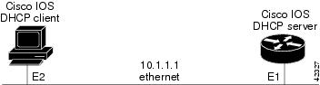
Cisco IOS DHCP Client Example
Figure 15 shows a simple network diagram of a DHCP client on an Ethernet LAN.
Figure 15 Topology Showing DHCP Client with Ethernet Interface
On the DHCP Server, the configuration is as follows:
network 10.1.1.0 255.255.255.0
On the DHCP client, the configuration is as follows on interface E2:
This configuration allows the DHCP client to aquire an IP address from the DHCP Server through an Ethernet interface.
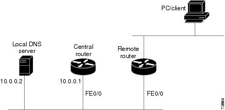
DHCP Server Options Import and Autoconfiguration Example
The following example shows a remote and central server configured to
support DHCP options import and autoconfiguration. The central server is
configured to automatically update DHCP options, such as DNS and WINs
addresses, within the DHCP pools. In response to a DHCP request from a
local client behind CPE equipment, the remote server can request or
"import" these option parameters from the centralized server. See Figure 16 for a diagram of the network topology.
Figure 16 DHCP Example Network Topology
Central Router
!do not assign this range to DHCP clients
ip dhcp-excluded address 10.0.0.1 10.0.0.5
! Specifies network number and mask for DHCP clients
network 10.0.0.0 255.255.255.0
! Specifes the domain name for the client
! Specifies DNS server that will respond to DHCP clients when they need to correlate host
! name to ip address
!Specifies the NETBIOS WINS server
netbios-name-server 10.0.0.2
interface FastEthernet0/0
ip address 10.0.0.1 255.255.255.0
Remote Router
! Imports DHCP options parameters into DHCP server database
network 20.0.0.0 255.255.255.0
interface FastEthernet0/0